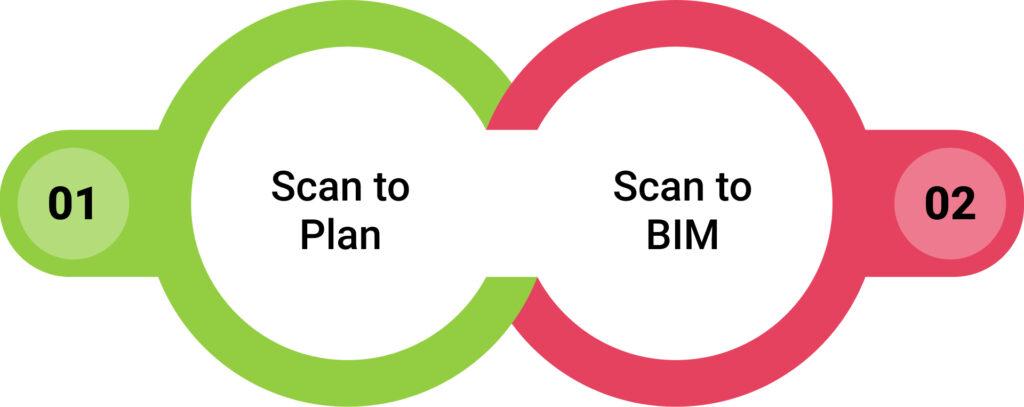
For construction teams navigating complex schedules, coordination demands, and digital deliverables, choosing between Scan to Plan and Scan to BIM is not a technical formality—it’s a strategic decision.
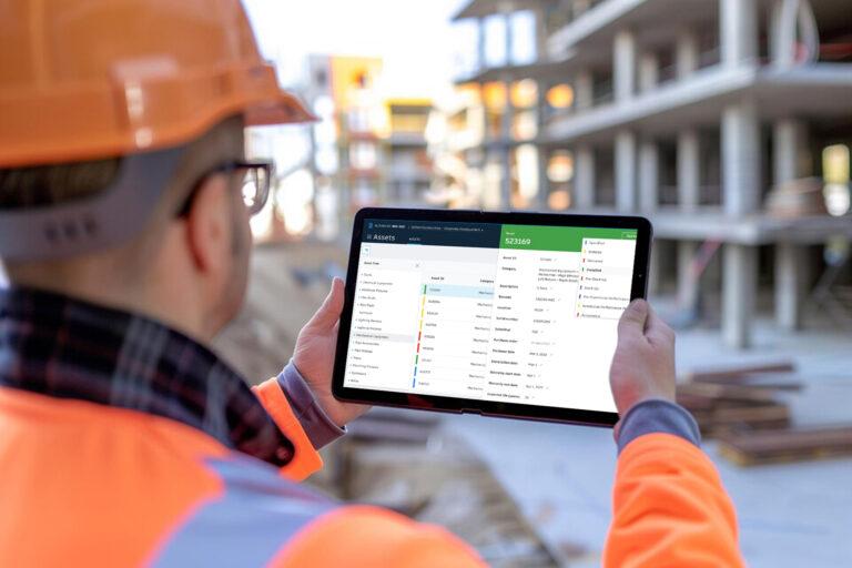
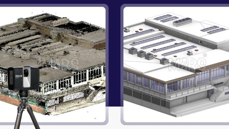
Laser scanning has become a reliable starting point for construction teams dealing with dense utility environments, aging infrastructure, and complex renovation scopes. From high-rise mechanical retrofits to interior layout validation, accurate site capture enables faster decisions and minimizes layout conflicts. The scanning process itself is standard, but how the data is processed into 2D plans or 3D BIM determines its usefulness during execution.
On-site crews, MEP coordinators, and subcontractors rely on actionable outputs that match the construction phase. Scan to Plan delivers CAD drawings suited for early-stage layouts, while Scan to BIM Services produces geometry-rich models that drive clash detection, prefabrication, and installation sequencing. Choosing the right format early helps control modeling costs, avoid rework, and support trade-specific workflows.
This guide supports project managers, VDC Manage leads, and field engineers who work under schedule pressure and coordination risk. It explains when to use Scan to Plan for speed and simplicity, and when Scan to BIM adds value through integration and detail. Aligning scanning outputs with project goals ensures smoother approvals, cleaner installs, and better construction outcomes.
Core Definitions in the Construction Context
Scan to Plan is used during the preconstruction phase when general contractors need fast, accurate 2D outputs to develop demolition scopes, layout markups, or permit sets. These CAD drawings are pulled directly from point cloud data and used on-site to validate dimensions before early-stage work begins. Construction teams often use them to verify wall offsets, ceiling heights, or slab edges without waiting for full modeling. It’s especially useful in fast-turnaround commercial interiors, strip mall renovations, and initial field inspections for core and shell upgrades.
Supports construction-phase coordination across trades particularly when routing mechanical, electrical, and plumbing systems in occupied or space-constrained environments. BIM outputs are modeled to match installation tolerances, not just design intent. VDC teams use this data for clash detection, fabrication planning, and install sequencing. These models are handed off to subcontractors during coordination meetings and integrated into platforms like Navisworks, Revizto, or BIM 360. For hospital retrofits, plant room overhauls, or datacenter expansions, Scan to BIM becomes essential for risk mitigation and precision execution.
Construction-Specific Decision Criteria
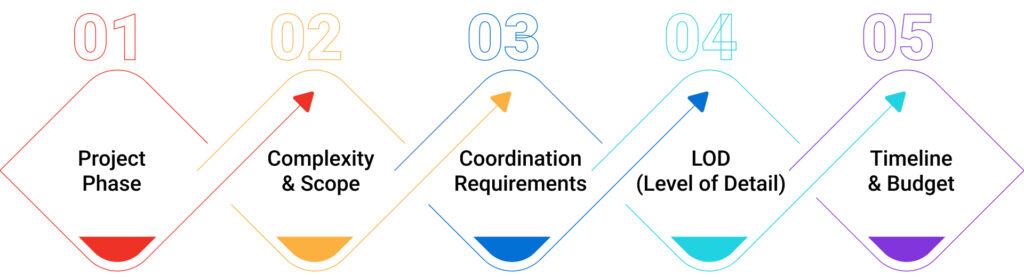
Project Phase
On renovation projects where slab layout and wall alignment must be confirmed before demo, Scan to Plan gives field engineers quick reference drawings to set saw-cut limits and protect structural members. During ceiling coordination, when MEP trades must finalize routing around existing beams or cable trays, Scan to BIM becomes the coordination backbone used in weekly clash resolution.
Complexity & Scope
In a single-floor retail refresh where ductwork and conduit are minimal, Scan to Plan allows quick dimension extraction and wall layout verification. In contrast, retrofit projects with existing shaft constraints, duct risers, or congested mechanical rooms demand Scan to BIM to avoid shutdown-triggering clashes or field-generated redesign.
Coordination Requirements
If trades are working independently with minimal overhead overlap, 2D plans may suffice. But when mechanical, plumbing, and fire suppression systems share tight ceiling corridors, Scan to BIM provides the 3D clarity needed to finalize routes, allocate clearances, and lock in sleeve locations before slab pours or wall closures.
LOD
When the field only needs general outlines for room sizing or layout stakeout, LOD 200 from Scan to Plan fits. For prefabrication-ready hanger plans, accurate flange clearances, or sleeve penetration points through structural decks, LOD 350+ from Scan to BIM ensures fabrication is based on real geometry, not guesswork.
Timeline & Budget
For quick-turn renovation scopes where coordination risk is low, teams use Scan to Plan to move into layout within 72 hours. On long-term projects with phasing, off-site prefabrication, or O&M deliverables, Scan to BIM justifies its higher upfront modeling time by reducing change orders, RFIs, and install delays across months of construction.
Real-World Use Cases
Scan to Plan
During selective demolition in an active manufacturing facility, the GC used Scan to Plan to generate accurate slab penetration maps. This allowed core-drilling crews to avoid post-tension cables without needing full structural modeling. In another project involving a partial façade removal on a high-rise, the contractor relied on 2D elevations extracted from scans to coordinate scaffold anchoring without waiting on as-built BIM.
When a subcontractor needed quick turnaround for layout reference in a fast-track retail rollout, 2D drawings generated from scans helped them locate HVAC return grilles and lighting junction boxes to match existing grid alignments before ceiling tile installation.
Scan to BIM
In a hospital MEP upgrade where downtime was limited to weekend windows, Scan to BIM was used to model the existing chilled water lines, electrical trays, and medical gas piping within congested interstitial spaces. This allowed the trades to resolve clearance conflicts digitally before sending spool sheets to fabrication eliminating field-cut delays. On a data center retrofit, the BIM model helped structural and mechanical teams plan bracing locations around live cable trays, avoiding accidental disruption of critical systems.
In a high-rise renovation with multiple riser zones, Scan to BIM supported vertical coordination across 20 floors by aligning electrical, sprinkler, and plumbing stacks within tight cores, eliminating rework during rough-in stages.
Advanced Benefits of Scan to BIM
- Validates hanger spacing around slab embeds before install, helping MEP trades avoid onsite bracket adjustments or dropped rod relocations.
- Identifies obstruction zones behind existing drywall (e.g., CMU chases, old conduit), allowing core teams to shift routing during coordination instead of mid-install.
- Optimizes prefabrication packaging by organizing ductwork or conduit bundles by zone, floor, or riser bay reducing staging congestion on tight sites.
- Accelerates layout using coordinated BIM-to-RTS exports, enabling field teams to set hundreds of points/day without manual chalk lines.
- Improves slab opening alignment across trades, ensuring structural, mechanical, and electrical sleeves line up before pour decks are shuttered.
- Supports real-time clash resolution during rolling coordination, especially in weekly meetings where trades are finalizing sequence per zone.
- Minimizes duct-drop conflicts in congested plenums, allowing early adjustment of offsets to protect lighting, sensors, or sprinkler heads.
- Enables phased access zone modeling, helping site managers plan scaffold drops, material hoists, or swing stages based on clash-free zones.
- Provides coordinated datum references for multi-level risers, ensuring pipe stacks remain plumb through 15–20 floor shafts without mid-course shifts.
Challenges in Scan to BIM Adoption

-
Trade Foremen Reject Models
On a hospital retrofit, the mechanical foreman flagged a modeled duct path with impossible 4″ clearance from fire suppression piping.
-
Solution
Engage trade leads in model reviews before LOD 300 sign-off. Don’t rely solely on Revit families verify with install crew logic.
-
Point Clouds Misaligned
Survey data often comes with misaligned levels or gridlines that don’t match actual slab edges or control lines already snapped onsite.
-
Solution:
Register point clouds to field-verified benchmarks. Let survey teams validate control lines using the same RTS used by layout crews.
-
Model Includes Legacy Systems
On phased retrofit jobs, older scans are used without checking for recent demo leading to coordination against non-existent systems.
-
Solution
Always re-scan active zones post-demo. Tag cloud zones by scan date and limit modeling to only “active” geometry confirmed in field.
-
Overmodeled Architectural Elements
LOD 400 walls with chamfers and recesses make the coordination model too heavy, delaying clash detection cycles.
-
Solution
Use LOD segmentation LOD 200 for architecture, LOD 350+ only for MEP zones that directly impact install.
-
Shutdown-Driven Projects
On industrial plants with 72-hour shutdown windows, there isn’t time to complete modeling, clash reviews, and revisions.
-
Solution
Use Scan to Plan for general layout and apply Scan to BIM selectively to high-risk routes like chemical piping or electrical switch overs.
-
Lack Access to In-Progress Field Changes
Install crews often reroute based on field conditions, but these changes aren’t captured in the model unless re-scanned.
-
Solution
Establish field-to-BIM feedback loop use laser scan updates weekly or enable site leads to tag changes via field apps tied to model zones.
Choosing the Right Tool
Choose Scan to Plan if:
- Quick 2D layout validation
- Small-scope renovation
- Fast-track site mobilization
Choose Scan to BIM if:
- Multi-trade coordination
- MEP prefabrication planning
- High-density ceiling routing
- Digital twin and FM integration
Final Thoughts
Construction teams often face costly delays when scan outputs do not match the coordination needs on site. Using full Scan to BIM in areas with simple scope drains time and budget, while relying on 2D drawings in congested MEP zones can lead to clashes, sleeve shifts, or incomplete prefabrication. Effective teams decide based on where risk is highest and where trades need precise alignment. Some projects assign Scan to Plan for open areas like open office floors, and reserve Scan to BIM for shaft stacking, interstitial coordination, or equipment-intensive zones. This targeted approach prevents rework and supports faster install.