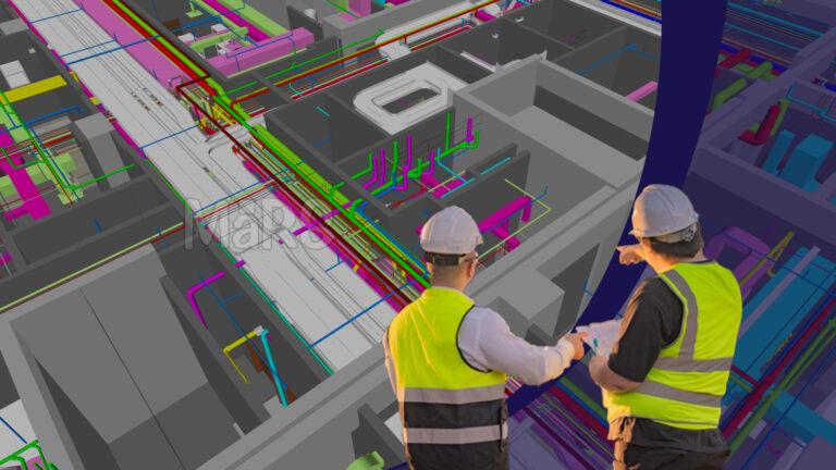
In the U.S. commercial construction sector, corporate buildings are evolving into highly integrated, performance-driven environments. These projects require detailed coordination of mechanical, electrical, and plumbing systems to support dense occupancy, flexible workspaces, data-intensive operations, and sustainability certifications such as LEED or WELL. Coordinating such infrastructure in tight timelines and complex structures has exposed the limitations of traditional coordination practices. 2D-based MEP layouts that lack spatial awareness and clash forecasting.
In projects involving stacked conference floors, executive zones, high-load server rooms, and distributed HVAC systems, even minor errors in MEP layout can lead to unbuildable conditions. misalignments in riser shafts, collisions in ceiling plenums, and last-minute equipment relocation requests cause costly disruptions. These issues often arise because conventional coordination workflows rely on fragmented drawing sets, delayed trade inputs, and reactive field adjustments, none of which are sustainable under compressed schedules and fixed budgets.
MEP BIM services in the USA have shifted from being a support tool to a strategic execution layer. Specialized BIM teams now engage early in design development, integrating system layouts directly into federated 3D environments, running clash checks across all trades, and aligning equipment data with fabrication and installation workflows. For corporate developments with mission-critical systems, this level of coordination isn’t optional. It’s important to achieve buildability, compliance, and turnover precision without compromising speed or cost.
A Complex Corporate Building in the USA
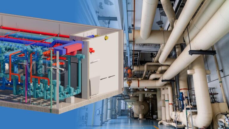
A corporate building project in the U.S. involves a high-rise commercial structure with advanced MEP requirements distributed across office floors, executive zones, data rooms, and service areas. These projects often include features like multi-zone HVAC systems, automated lighting controls, backup generators, pressure-regulated plumbing risers, and integrated fire protection. All are layered within limited ceiling plenums and vertical shafts. For projects focused on research-driven operations, R&D industrial building MEP BIM modeling plays a central role in aligning environmental systems with technical space needs, equipment zones, and regulatory benchmarks for safety and efficiency.
The execution framework includes developers, design consultants, trade contractors, and a dedicated BIM and VDC Services team coordinating across platforms. MEP systems often drive key milestones such as shaft opening placement, slab penetration approvals, and long-lead equipment procurement. U.S.-based MEP BIM experts contribute by building discipline-specific 3D models that align with fabrication logic, installation tolerances, and inspection requirements. Their models support trade-level detailing while enabling cross-disciplinary coordination, allowing system installation, inspection, and commissioning workflows to proceed without interruption.
Challenges with Traditional MEP Coordination
- Misaligned shaft openings between MEP layouts and structural cores resulted in unapproved site drilling and rework
- Overlapping HVAC ducts, cable trays, and fire lines within tight ceiling plenums created major conflicts during installation
- Uncoordinated trade sequencing in riser cores led to blocked access for electrical and plumbing contractors
- Late-stage equipment submittals with revised dimensions disrupted frozen layouts and impacted prefabrication schedules
- Plumbing systems lacked accurate slope representation, causing elevation mismatches with structural beams
- Mechanical equipment rooms were planned without validating real clearance for access, maintenance, or piping connectivity
- Manual markups and isolated coordination efforts introduced inconsistencies between drawings and actual field conditions
Strategic Implementation of MEP BIM Services
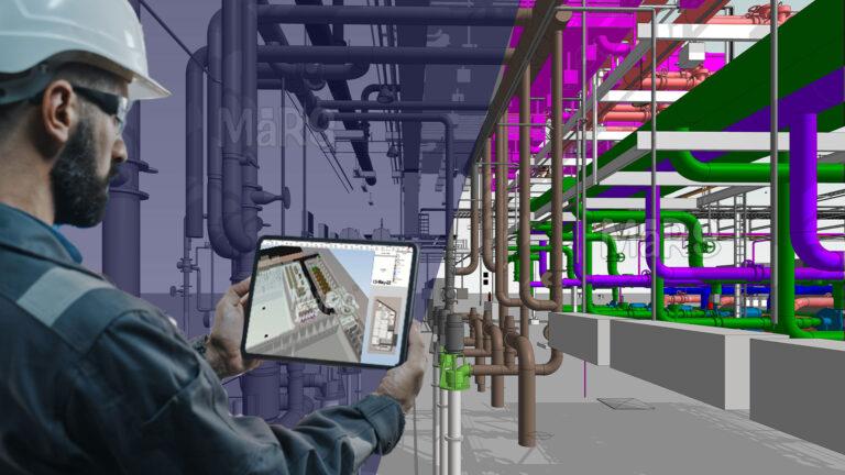
The project team engaged MEP BIM specialists during the early design coordination phase to align system routing with structural and architectural constraints. Instead of using generic content or post-design modeling, the BIM scope focused on translating design intent into trade-executable detail. Each system was modeled based on fabrication requirements, zone-specific clearance checks, and contractor sequencing logic. Coordination was conducted using real-time issue tracking in BIM 360, with weekly reviews tied directly to installation areas such as risers, mechanical rooms, and high-density ceiling zones. This proactive workflow enabled early decision-making for sleeve embed approvals, hanger layouts, and equipment submittal integration.
Key Points
- MEP BIM team collaborated with structure and architecture to reserve service zones in early planning
- Hanger, sleeve, and penetration locations were locked before slab pour deadlines using embedded models
- Revit families included mounting constraints, clearances, and fitting rules based on actual shop submittals
- Weekly clash detection focused on critical areas first—risers, shafts, low-floor corridors, and switchgear rooms
- BIM 360 dashboards tracked open issues, assigned trades, and resolution deadlines for faster accountability
- Model iterations were version-controlled and mapped to field sequencing packages for smoother deployment
Lock sleeve and hanger locations in the BIM model at least two weeks ahead of pour dates. This allows prefabrication to begin without field changes, especially in high-pressure zones like data rooms and mechanical shafts.
Impact and Benefits Realized
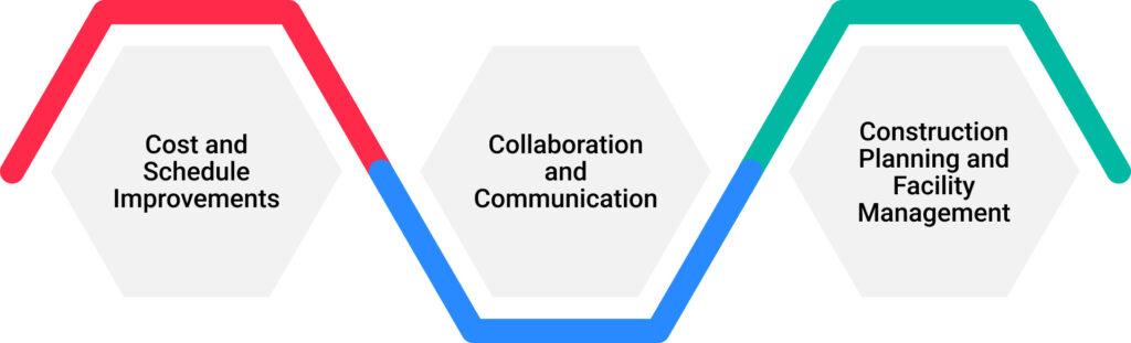
Cost and Schedule Improvements
MEP BIM Coordination significantly improved planning precision, especially in vertical shafts, mechanical rooms, and ceiling routing zones. Over 280 system conflicts were resolved during early design coordination cycles, preventing delays tied to field interference and redesign. Equipment such as AHUs, VFD panels, and water boosters were placed with verified clearance before slab pours. Coordinated support systems and sleeve maps allowed prefabrication to begin ahead of schedule, cutting installation time by over two weeks across mechanical and plumbing trades.
Collaboration and Communication
A centralized BIM environment provided real-time access to design progress, trade-specific routing updates, and approval tracking. During weekly reviews, the BIM team shared visual heat maps and zone-based issue logs for areas like pump rooms, riser banks, and switchgear corridors. Each item was tagged by location, discipline, and urgency—helping field supervisors prioritize and resolve over 85% of pending design issues within the scheduled coordination cycle. The digital-first approach improved communication flow between VDC teams, engineers, and field foremen.
Construction Planning and Facility Management
With installation-ready BIM data, hanger locations, sleeve penetrations, and module boundaries were validated well before field execution. This enabled precise slab penetrations and preapproved MEP zones across floors. Once construction was complete, the coordinated model was enriched with actual equipment metadata, service tag references, and maintenance paths. The structured asset model now supports long-term maintenance planning and digital facilities management, helping the owner streamline energy audits, spare part tracking, and retrofit studies.
In a multi-level corporate project, the MEP BIM team created floor-specific shaft layouts to accommodate differences in electrical load centers and core wall offsets. Each level’s vertical services were prioritized and stacked based on system criticality, fire rating, and space availability. This avoided alignment issues across levels and allowed mechanical and electrical trades to prefabricate riser sections with minimal adjustments during site install.
Key Lessons for AEC Professionals
- Begin MEP BIM integration before structural layout freeze to ensure shaft sizes and slab openings reflect real routing needs
- Prioritize zone-based modeling for risers and corridors to manage elevation shifts across floors and avoid installation delays
- Create trade-specific modeling scopes where electrical, plumbing, and HVAC each follow fabrication constraints from day one
- Use approved equipment submittals to build Revit families early, avoiding remobilization due to late dimensional changes
- Reserve ceiling space based on installation order and access needs—avoid routing overlaps by sequencing per trade logic
- Coordinate hanger and support layouts directly from the BIM model to reduce field rework and minimize deviation requests
- Assign resolution timelines to model issues and tie them to critical field activities like shaft framing or equipment lifts
- Capture system segmentation like VAV zones and plumbing branches in the model to support both installation phasing and testing plans
Conclusion
Executing MEP systems in complex corporate buildings requires coordination strategies that reflect real site constraints, system interdependencies, and trade-specific workflows. MEP BIM services in the USA supported this process by enabling early layout validation, system zoning, and clash-free installation planning across shafts, mechanical rooms, and ceiling spaces. By integrating equipment submittals, hanger logic, and sleeve positioning into the model, teams were able to finalize routing before construction, accelerate prefabrication, and reduce field rework. The structured model also supported accurate handover documentation for operations teams. For AEC professionals delivering technically intensive commercial buildings, MEP BIM serves as a coordination framework that ensures precision, sequencing clarity, and reduced execution risk.